Frequency Modulation
Frequency Modulation
In telecommunications and signal processing, frequency modulation (FM) is the encoding of information in a carrier wave by varying the instantaneous frequency of the wave.
In analog frequency modulation, such as FM radio broadcasting of an audio signal representing voice or music, the instantaneous frequency deviation, the difference between the frequency of the carrier and its center frequency, is proportional to the modulating signal.
Waveform
The frequency of a carrier (fc) will increase as the amplitude of modulating (input) signal increases. The carrier frequency will be maximum (fc max) when the input signal is at its peak. The carrier deviates maximum from its normal value. The frequency of a carrier will decrease as the amplitude of the modulating (input) signal decreases. The carrier frequency will be minimum (fc min) when the input signal is at its lowest. The carrier deviates minimum from its normal value. The frequency of the carrier will be at its normal value (free running) fc when the input signal value is 0V. There is no deviation in the carrier. The figure shows the frequency of the FM wave when the input is at its max, 0V and at its min.

FM Spectrum
A spectrum represents the relative amounts of different frequency components in any signal. Its like the display on the graphic-equalizer in your stereo which has leds showing the relative amounts of bass, midrange and treble. These correspond directly to increasing frequencies (treble being the high frequency components). It is a well-know fact of mathematics, that any function (signal) can be decomposed into purely sinusoidal components (with a few pathological exceptions) . In technical terms, the sines and cosines form a complete set of functions, also known as a basis in the infinite-dimensional vector space of real-valued functions (gag reflex). Given that any signal can be thought to be made up of sinusoidal signals, the spectrum then represents the "recipe card" of how to make the signal from sinusoids.
The spectrum of a simple FM signal looks like

The carrier is now 65 Hz, the modulating signal is a pure 5 Hz tone, and the modulation index is 2. What we see are multiple side-bands (spikes at other than the carrier frequency) separated by the modulating frequency, 5 Hz. There are roughly 3 side-bands on either side of the carrier. The shape of the spectrum may be explained using a simple heterodyne argument: when you mix the three frequencies (fc, fm and Df) together you get the sum and difference frequencies. The largest combination is fc + fm + Df, and the smallest is fc - fm - Df. Since Df = b fm, the frequency varies (b + 1) fm above and below the carrier.
Bandwidth
As we have already shown, the bandwidth of a FM signal may be predicted using:
BW = 2 (b + 1 ) fm
where b is the modulation index and
fm is the maximum modulating frequency used.
FM radio has a significantly larger bandwidth than AM radio, but the FM radio band is also larger. The combination keeps the number of available channels about the same.
The bandwidth of an FM signal has a more complicated dependency than in the AM case (recall, the bandwidth of AM signals depend only on the maximum modulation frequency). In FM, both the modulation index and the modulating frequency affect the bandwidth. As the information is made stronger, the bandwidth also grows.
Efficiency
The efficiency of a signal is the power in the side-bands as a fraction of the total. In FM signals, because of the considerable side-bands produced, the efficiency is generally high. Recall that conventional AM is limited to about 33 % efficiency to prevent distortion in the receiver when the modulation index was greater than 1. FM has no analogous problem.
Noise
FM systems are far better at rejecting noise than AM systems. Noise generally is spread uniformly across the spectrum (the so-called white noise, meaning wide spectrum). The amplitude of the noise varies randomly at these frequencies. The change in amplitude can actually modulate the signal and be picked up in the AM system. As a result, AM systems are very sensitive to random noise. An example might be ignition system noise in your car. Special filters need to be installed to keep the interference out of your car radio.
FM Generation circuits
1. Direct Method
1) Reactance Modulator
A reactance modulator changes the frequency of the tank circuit of the oscillator by changing its reactance. This is accomplished by a combination of a resistor, a condenser, and a vacuum tube (the modulator) connected across the tank circuit of the oscillator as in Fig. 33 A, and so adjusted as to act as a variable inductance or capacitance.

The net result is to change the resonant frequency of the LC circuit by amounts proportional to the instantaneous a.f. voltages applied to the grid of the modulator tube, without changing the resistance of the LC circuit or the amplitude of the oscillations. A modulator circuit is shown in the figure

Ref:- http://www.vias.org/basicradio/basic_radio_34_02.html
the radio-frequency voltages which are developed across the tank in the oscillator circuit also appear across the RC1 circuit and across the parallel 6L7 modulator tube. Now look up the phase-shifting circuit of Fig. 19 H. The resistance r has been replaced by the internal resistance of the modulator tube of Fig. 33 B. The voltage drop across C1 is 90° out of phase with the tank voltage. It is applied to the control grid of the 6L7 whose r.f. plate current responds in the same phase. Thus this current is made to lag 90° behind the tank voltage. The r.f. plate current flows through the tank circuit and, combined with the current therein, is equivalent to a new current whose phase differs from the normal value just as though an additional reactance (not resistance) had been connected in with L and C. This, of course, changes the frequency of the LC circuit and hence of the transmitter. When a.f. is fed into the modulator tube, it causes proportionate changes in the r.f. plate current and hence in the equivalent reactance of the LC circuit.
2) Varactor Diode modulator
Figure shows the basic concept of a varactor frequency modulator. The L, and C represent the tuned circuit of the carrier oscillator. Varactor diode D is connected in series with capacitor C, across the tuned circuit. The value of C is made very large at the operating frequency series with the lower capacitance of so that its reactance is very low. As a result, when C, is connected in D, the effect is as if D, were connected directly across the tuned circuit. The total effective circuit capacitance then is the capacitance of D, in parallel with C. This fixes the center carrier frequency

Ref:- https://www.daenotes.com/electronics/communication-system/varactor-diode-modulator
The Varactor Diode Modulator capacitance of D, of course, is controlled by two factors: a fixed dc bias and the modulating signal. In Fig b, the bias on D, is set by the voltage divider which is made up of R, and R2. Usually either R, or R2 is made variable so that the center carrier frequency can be adjusted over a narrow range. The modulating signal is applied through C3 and the RFC. The Cz is a blocking capacitor that keeps the DC bias out of the modulating signal circuits. The RFC is a radio frequency choke whose reactance is high at the carrier frequency to prevent the carrier signal from getting into the the modulating signal circuits. The modulating signal derived from the microphone is amplified and applied to modulator. As the modulating signal varies, it adds to or subtracts from the fixed bias voltage. Thus the effective voltage applied to D, causes its capacitance to vary. This, in turn, produces a deviation of the carrier frequency as desired. A positive-going signal at point A adds to the reverse bias, decreasing the capacitance and increasing the carrier frequency. A negative-going signal at A subtracts from the bias, increasing the capacitance and decreasing the carrier frequency.
2. Indirect method
The part of the Armstrong FM transmitter (Armstrong phase modulator) which is expressed in dotted lines describes the principle of operation of an Armstrong phase modulator. It should be noted, first that the output signal from the carrier oscillator is supplied to circuits that perform the task of modulating the carrier signal. The oscillator does not change frequency, as is the case of direct FM. These points out the major advantage of phase modulation (PM), or indirect FM, over direct FM. That is the phase modulator is crystal controlled for frequency.

Ref:- https://www.daenotes.com/electronics/communication-system/armstrong-fm-transmitter
FM detectors Circuit
1. Balanced Slope Detectors
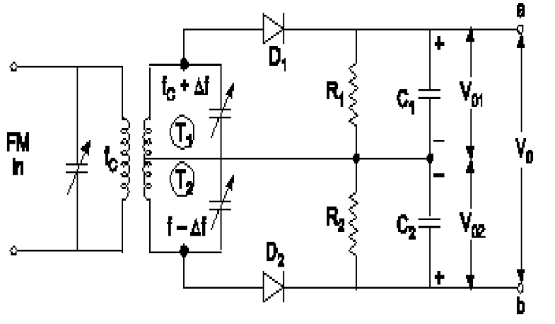
It can be seen from the diagram that changes in the slope of the filter, reflect into the linearity of the demodulation process. The linearity is very dependent not only on the filter slope as it falls away, but also the tuning of the receiver - it is necessary to tune the receiver off frequency and to a pint where the filter characteristic is relatively linear.
The final stage in the process is to demodulate the amplitude modulation and this can be achieved using a simple diode circuit. One of the most obvious disadvantages of this simple approach is the fact that both amplitude and frequency variations in the incoming signal appear at the output. However the amplitude variations can be removed by placing a limiter before the detector.
2. Foster Seeley Discriminator
The Foster–Seeley discriminator is a common type of FM detector circuit, invented in 1936 by Dudley E. Foster and Stuart William Seeley. The circuit was envisioned for automatic frequency control of receivers, but also found application in demodulating an FM signal. It uses a tuned RF transformer to convert frequency changes into amplitude changes. A transformer, tuned to the carrier frequency, is connected to two rectifier diodes. The circuit resembles a full-wave bridge rectifier. If the input equals the carrier frequency, the two halves of the tuned transformer circuit produce the same rectified voltage and the output is zero. As the frequency of the input changes, the balance between the two halves of the transformer secondary changes, and the result is a voltage proportional to the frequency deviation of the carrier.

In telecommunications and signal processing, frequency modulation (FM) is the encoding of information in a carrier wave by varying the instantaneous frequency of the wave.
In analog frequency modulation, such as FM radio broadcasting of an audio signal representing voice or music, the instantaneous frequency deviation, the difference between the frequency of the carrier and its center frequency, is proportional to the modulating signal.
Waveform
The frequency of a carrier (fc) will increase as the amplitude of modulating (input) signal increases. The carrier frequency will be maximum (fc max) when the input signal is at its peak. The carrier deviates maximum from its normal value. The frequency of a carrier will decrease as the amplitude of the modulating (input) signal decreases. The carrier frequency will be minimum (fc min) when the input signal is at its lowest. The carrier deviates minimum from its normal value. The frequency of the carrier will be at its normal value (free running) fc when the input signal value is 0V. There is no deviation in the carrier. The figure shows the frequency of the FM wave when the input is at its max, 0V and at its min.
FM Spectrum
A spectrum represents the relative amounts of different frequency components in any signal. Its like the display on the graphic-equalizer in your stereo which has leds showing the relative amounts of bass, midrange and treble. These correspond directly to increasing frequencies (treble being the high frequency components). It is a well-know fact of mathematics, that any function (signal) can be decomposed into purely sinusoidal components (with a few pathological exceptions) . In technical terms, the sines and cosines form a complete set of functions, also known as a basis in the infinite-dimensional vector space of real-valued functions (gag reflex). Given that any signal can be thought to be made up of sinusoidal signals, the spectrum then represents the "recipe card" of how to make the signal from sinusoids.
The spectrum of a simple FM signal looks like
The carrier is now 65 Hz, the modulating signal is a pure 5 Hz tone, and the modulation index is 2. What we see are multiple side-bands (spikes at other than the carrier frequency) separated by the modulating frequency, 5 Hz. There are roughly 3 side-bands on either side of the carrier. The shape of the spectrum may be explained using a simple heterodyne argument: when you mix the three frequencies (fc, fm and Df) together you get the sum and difference frequencies. The largest combination is fc + fm + Df, and the smallest is fc - fm - Df. Since Df = b fm, the frequency varies (b + 1) fm above and below the carrier.
Bandwidth
As we have already shown, the bandwidth of a FM signal may be predicted using:
BW = 2 (b + 1 ) fm
where b is the modulation index and
fm is the maximum modulating frequency used.
FM radio has a significantly larger bandwidth than AM radio, but the FM radio band is also larger. The combination keeps the number of available channels about the same.
The bandwidth of an FM signal has a more complicated dependency than in the AM case (recall, the bandwidth of AM signals depend only on the maximum modulation frequency). In FM, both the modulation index and the modulating frequency affect the bandwidth. As the information is made stronger, the bandwidth also grows.
Efficiency
The efficiency of a signal is the power in the side-bands as a fraction of the total. In FM signals, because of the considerable side-bands produced, the efficiency is generally high. Recall that conventional AM is limited to about 33 % efficiency to prevent distortion in the receiver when the modulation index was greater than 1. FM has no analogous problem.
Noise
FM systems are far better at rejecting noise than AM systems. Noise generally is spread uniformly across the spectrum (the so-called white noise, meaning wide spectrum). The amplitude of the noise varies randomly at these frequencies. The change in amplitude can actually modulate the signal and be picked up in the AM system. As a result, AM systems are very sensitive to random noise. An example might be ignition system noise in your car. Special filters need to be installed to keep the interference out of your car radio.
FM Generation circuits
1. Direct Method
1) Reactance Modulator
A reactance modulator changes the frequency of the tank circuit of the oscillator by changing its reactance. This is accomplished by a combination of a resistor, a condenser, and a vacuum tube (the modulator) connected across the tank circuit of the oscillator as in Fig. 33 A, and so adjusted as to act as a variable inductance or capacitance.
The net result is to change the resonant frequency of the LC circuit by amounts proportional to the instantaneous a.f. voltages applied to the grid of the modulator tube, without changing the resistance of the LC circuit or the amplitude of the oscillations. A modulator circuit is shown in the figure
Ref:- http://www.vias.org/basicradio/basic_radio_34_02.html
the radio-frequency voltages which are developed across the tank in the oscillator circuit also appear across the RC1 circuit and across the parallel 6L7 modulator tube. Now look up the phase-shifting circuit of Fig. 19 H. The resistance r has been replaced by the internal resistance of the modulator tube of Fig. 33 B. The voltage drop across C1 is 90° out of phase with the tank voltage. It is applied to the control grid of the 6L7 whose r.f. plate current responds in the same phase. Thus this current is made to lag 90° behind the tank voltage. The r.f. plate current flows through the tank circuit and, combined with the current therein, is equivalent to a new current whose phase differs from the normal value just as though an additional reactance (not resistance) had been connected in with L and C. This, of course, changes the frequency of the LC circuit and hence of the transmitter. When a.f. is fed into the modulator tube, it causes proportionate changes in the r.f. plate current and hence in the equivalent reactance of the LC circuit.
2) Varactor Diode modulator
Figure shows the basic concept of a varactor frequency modulator. The L, and C represent the tuned circuit of the carrier oscillator. Varactor diode D is connected in series with capacitor C, across the tuned circuit. The value of C is made very large at the operating frequency series with the lower capacitance of so that its reactance is very low. As a result, when C, is connected in D, the effect is as if D, were connected directly across the tuned circuit. The total effective circuit capacitance then is the capacitance of D, in parallel with C. This fixes the center carrier frequency
Ref:- https://www.daenotes.com/electronics/communication-system/varactor-diode-modulator
The Varactor Diode Modulator capacitance of D, of course, is controlled by two factors: a fixed dc bias and the modulating signal. In Fig b, the bias on D, is set by the voltage divider which is made up of R, and R2. Usually either R, or R2 is made variable so that the center carrier frequency can be adjusted over a narrow range. The modulating signal is applied through C3 and the RFC. The Cz is a blocking capacitor that keeps the DC bias out of the modulating signal circuits. The RFC is a radio frequency choke whose reactance is high at the carrier frequency to prevent the carrier signal from getting into the the modulating signal circuits. The modulating signal derived from the microphone is amplified and applied to modulator. As the modulating signal varies, it adds to or subtracts from the fixed bias voltage. Thus the effective voltage applied to D, causes its capacitance to vary. This, in turn, produces a deviation of the carrier frequency as desired. A positive-going signal at point A adds to the reverse bias, decreasing the capacitance and increasing the carrier frequency. A negative-going signal at A subtracts from the bias, increasing the capacitance and decreasing the carrier frequency.
2. Indirect method
The part of the Armstrong FM transmitter (Armstrong phase modulator) which is expressed in dotted lines describes the principle of operation of an Armstrong phase modulator. It should be noted, first that the output signal from the carrier oscillator is supplied to circuits that perform the task of modulating the carrier signal. The oscillator does not change frequency, as is the case of direct FM. These points out the major advantage of phase modulation (PM), or indirect FM, over direct FM. That is the phase modulator is crystal controlled for frequency.
Ref:- https://www.daenotes.com/electronics/communication-system/armstrong-fm-transmitter
FM detectors Circuit
1. Balanced Slope Detectors
It can be seen from the diagram that changes in the slope of the filter, reflect into the linearity of the demodulation process. The linearity is very dependent not only on the filter slope as it falls away, but also the tuning of the receiver - it is necessary to tune the receiver off frequency and to a pint where the filter characteristic is relatively linear.
The final stage in the process is to demodulate the amplitude modulation and this can be achieved using a simple diode circuit. One of the most obvious disadvantages of this simple approach is the fact that both amplitude and frequency variations in the incoming signal appear at the output. However the amplitude variations can be removed by placing a limiter before the detector.
2. Foster Seeley Discriminator
The Foster–Seeley discriminator is a common type of FM detector circuit, invented in 1936 by Dudley E. Foster and Stuart William Seeley. The circuit was envisioned for automatic frequency control of receivers, but also found application in demodulating an FM signal. It uses a tuned RF transformer to convert frequency changes into amplitude changes. A transformer, tuned to the carrier frequency, is connected to two rectifier diodes. The circuit resembles a full-wave bridge rectifier. If the input equals the carrier frequency, the two halves of the tuned transformer circuit produce the same rectified voltage and the output is zero. As the frequency of the input changes, the balance between the two halves of the transformer secondary changes, and the result is a voltage proportional to the frequency deviation of the carrier.


Comments
Post a Comment